 Download
Umbrella Arch Pipe Roof Support: Key Techniques Overview
Time:2026-03-17From:sinorock View:
Pipe roof support (also known as pipe umbrella, umbrella arch, long pipe roof, fore poling with pipes, or pipe canopy) is a widely used advanced pre-support technique in underground engineering.
Core Principle
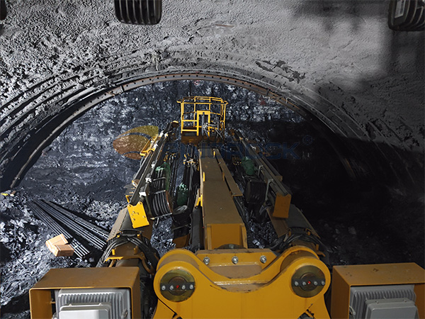
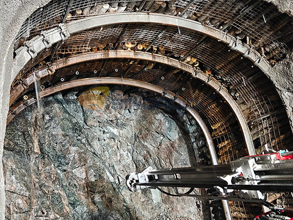
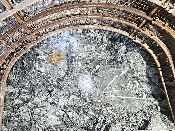
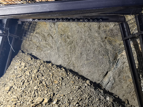
Before excavation, a series of steel pipes are installed along or slightly outside the tunnel crown contour in the ground ahead of the face. These pipes form an arched “umbrella” or “canopy” structure that transfers overburden pressure longitudinally through arch action to the already excavated and stabilized side walls or base, significantly reducing early loosening, deformation, and collapse risk at the excavation face and crown.
Main Classifications
· Conventional pipe roof (drill hole → insert pipe → grout): Suitable for most ground conditions.
· Self-drilling pipe roof (self-drilling hollow grout-injectable pipes): Drilling, installation, and grouting occur simultaneously; faster and collapse-resistant, ideal for loose sand-gravel, flowing sand, or highly fractured zones.
· Short pipe roof (9–15 m): Cyclic advancement method.
· Long pipe roof (20–50 m+): Used for shallow-buried large-span sections, portal areas, or extended advance protection.
Application Scenarios
Particularly suitable for ground with poor self-stability, high collapse risk, and strict settlement control requirements. It has become one of the preferred advance support methods in urban shallow-buried tunneling.
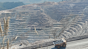
· Mine roadway portals and fault/fracture zone crossings.
· Shallow and ultra-shallow buried sections of urban metro, railway, and highway tunnels (cover depth < 30 m).
· Large-span metro stations, cross passages, and running tunnels in sand, sandy gravel, silty clay, water-rich loose strata.
· Temporary crown protection during deep foundation pit or basement excavation.
· Tunneling beneath buildings, utilities, or sensitive structures requiring strict surface settlement control.
· Remediation of collapsed sections or re-excavation of old tunnels.
Construction Process
1. Survey and layout → precise positioning of crown pipe holes (total station, outward inclination 1°–5°).
2. Drilling (with casing or follow-the-pipe drilling to prevent hole collapse).
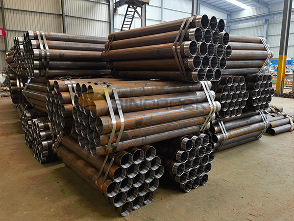
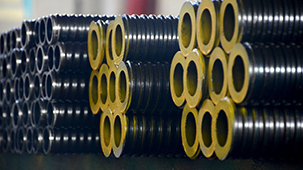
3. Insert steel pipes (φ108–φ180 mm, wall thickness 6–12 mm, with grout holes).
4. Pipe end treatment: front end with grout stopper or perforated section; rear end with flange/threaded connection.
5. Grouting (cement-water glass double-liquid grout or single cement grout, pressure 0.5–3.0 MPa).
6. Connect pipes (welding or threaded coupling) to form a continuous arch.
7. Install lattice girders or steel sets (I20b–I25b) and connect to pipe roof for integrated load bearing.
8. Apply shotcrete (C25–C30. thickness ≥150 mm) to seal pipes and surrounding ground.
9. Excavate face (bench method, CD method, PBA method; advance per cycle 0.5–1.5 m).
10. Install next ring of pipes (longitudinal overlap ≥3–5 m for continuity).
Design Parameters
| Parameter | Typical Range | Remarks |
| Pipe outer diameter | φ108–φ180 mm | Urban metro often uses φ127 / φ159 |
| Wall thickness | 6–12 mm | Increase in water-rich ground |
| Pipe length | 9–50 m | Short: 9–15 m; Long: 30–50 m+ |
| Outward inclination | 1°–5° | Shallower cover → smaller angle |
| Circumferential spacing | 30–50 cm | Closer in sand; wider in rock |
| Longitudinal overlap | ≥3–5 m | Ensures continuous load transfer |
| Grouting pressure | 0.5–3.0 MPa | Segmented pressure increase to avoid leakage |
| Grout diffusion radius | 0.5–1.5 m | Depends on ground permeability |
| Arch coverage angle | 120°–180° | Larger spans → near full ring coverage |
Technical Advantages
· Long advance distance (up to 30–50 m+), providing ample preparation time in difficult ground.
· Strong arching effect transfers load longitudinally, greatly improving face stability.
· Excellent control of surface settlement (preferred method in urban shallow tunneling).
· Dual function as water-stop curtains after effective grouting.
· Highly compatible with lattice girders, shotcrete, rock bolts, self-drilling anchors, etc.
· Relatively mechanized process using horizontal directional drilling rigs.
Limitations
High equipment demand: Requires large horizontal drilling rigs; difficult in confined urban sites.
Drilling challenges: Boulders, cobbles, high-pressure water-bearing zones can cause jamming, deviation, or collapse.
Higher cost: Steel pipes, grouting materials, and drilling are expensive (especially long pipe roofs).
Grouting performance depends on ground: Severe grout loss in highly permeable strata; limited effectiveness in very soft flowing ground (e.g., silt, quicksand) → may need ground freezing, jet grouting, or large-diameter multi-row systems.
Longer construction cycle: One long pipe roof ring may take weeks, impacting overall schedule.
Not suitable for: Very hard rock (low drilling efficiency), extremely shallow cover (<5 m, high risk of daylighting/breakthrough), or vibration-sensitive precision facilities nearby.
Combined Use with Self-Drilling Anchors
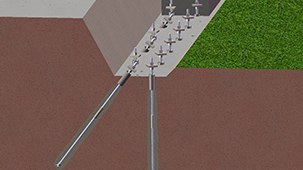
The combination of pipe roof (shallow arch pre-support) + self-drilling anchors (deep reinforcement) is currently one of the most effective “dual advance support systems” in complex ground:
Pipe roof → carries shallow crown load, prevents early collapse and major deformation.
Self-drilling anchors (φ32–φ51 mm, length 4–12 m) → radially or umbrella-pattern installed, anchored into deeper stable strata, providing long-term tensile resistance and controlling medium- to long-term convergence.
Combined effect: Creates a “shallow rigid arch + deep flexible anchorage” composite system, especially effective in water-rich sandy gravel, fractured rock, and shallow large-span tunnels.
Safety Control Key Points
· Surface settlement and building tilt (alert value: 10–20 mm).
· Crown and peripheral convergence (alert value: 20–50 mm).
· Pipe roof stress/deflection (strain gauges or inclinometers).
· Groundwater level and inflow volume.
· Face stability visual inspection (cracks, spalling, sand flow).
· Strictly prohibit over-excavation, limit exposed face time per design.
· Confirm grout strength (≥28 days) before each excavation cycle.
· Install water-stop curtains + drainage holes in water-rich ground.
· Prepare emergency plans for collapse, mud inrush, water inrush.
Conclusion
Pipe roof support has become an indispensable advance pre-support core technology in modern underground engineering — particularly in urban shallow-buried tunneling — due to its long advance distance, high stiffness, excellent settlement control, and strong adaptability.
When combined with self-drilling anchors, lattice girders, shotcrete, and other elements, it forms a highly efficient and safe composite support system, providing reliable assurance for rapid and safe construction under complex geological conditions.
latest news
-
- Mine Support and Stabilization Technology: Self-Drilling Anchor Bolt Systems
- Time:2026-04-23From:This Site
- Professional mine support solutions integrating drilling, pipe roof processes, and self-drilling anchors to ensure stable, safe, and efficient operations for both underground and open-pit mines.
- View details
-
- Self-Drilling Anchor Bolt Systems in Railway Tunnels: Applications and Standards
- Time:2026-04-21From:This Site
- Explore the applications and international standards of self-drilling anchor bolt systems in railway tunnels. Learn how they enhance slope, tunnel, and bridge stability for safer railway infrastructure.
- View details
-
- Self-Drilling Anchor Bolts for Micropiles: Complete Geotechnical Engineering Guide
- Time:2026-04-18From:This Site
- Explore the benefits of SDA bolt micropiles for constrained construction sites, complex geology, and rapid installation. Case studies and practical guidelines included.
- View details
-
- Sinorock 2025 Quality Month | Strengthening Quality Foundations, Empowering Product Excellence
- Time:2025-08-13From:This Site
- Sinorock’s 2025 Quality Month, themed “Strengthening Quality Foundations, Empowering Product Excellence,” successfully concluded, reinforcing our commitment to superior product quality.
- View details
-
- Sinorock Safety Month 2025 | Everyone Speaks Safety, Everyone Can Respond
- Time:2025-07-03From:This Site
- Sinorock Safety Month 2025, centered on the theme "Everyone Speaks Safety, Everyone Can Respond - Spot Workplace Hazards," has wrapped up successfully!
- View details
-
- Quality Control: the Vital Factor of A SDA Bolt Factory
- Time:2025-01-09From:This Site
- Sinorock’s comprehensive quality control system, from supplier management to outgoing inspections, ensuring the highest standards for self-drilling anchor bolts in construction.
- View details
-
- Sinorock Invites You to Visit Us at CONEXPO-CON/AGG
- Time:2026-02-14From:This Site
- Sinorock Invites You to Explore Proven Self-Drilling Anchor Bolt Solutions at CONEXPO-CON/AGG –S63341.South Hall 1st Level
- View details
-

- SINOROCK to Showcase Innovative Mining Solutions at Mining and Metals Central Asia 2025
- Time:2025-09-09From:This Site
- We are pleased to share that SINOROCK will participate in the Mining and Metals Central Asia 2025, taking place from September 17 to 19 at the Atakent International Exhibition Centre in Almaty, Kazakhstan. You can find us at Booth 11-231.
- View details
-
- Sinorock Invites You to Explore Proven Self-Drilling Anchor Bolt Solutions at bauma 2025
- Time:2025-03-07From:This Site
- From April 7–13, 2025, explore Sinorock’s Self-drilling anchor bolt solution at Booth C2.513/4 in Hall C2 of the Messe München Exhibition Center (Munich, Germany).
- View details
